Posts

Showing posts from July, 2020

previous post

RICH DAD POOR DAD BOOK REVIEW

  RICH  DAD  POOR  DAD  BOOK REVIEW This is amazing book.   • Explodes the myth that you need to earn a high income to become rich • Challenges the belief that your house is an asset • Shows parents why they can't rely on the school system to teach their kids about money • Defines once and for all an asset and a liability • Teaches you what to teach your kids about money for their future financial success It's been nearly 25 years since Robert Kiyosaki’s  Rich Dad Poor Dad  first made waves in the Personal Finance arena. It has since become the #1 Personal Finance book of all time... translated into dozens of languages and sold around the world. Rich Dad Poor Dad  is Robert's story of growing up with two dads — his real father and the father of his best friend, his rich dad — and the ways in which both men shaped his thoughts about money and investing. The book explodes the myth that you need to earn a high income to be rich and explains the difference between working

CLASSIFICATION OF DC MACHINE

Image
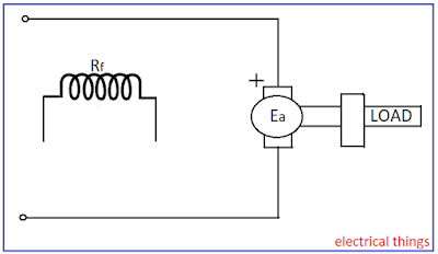
Classification of DC Machine DC Machines have been classified into multiple categories based on the connection of field winding and armature winding. The connections are mentioned below :- Separately Excited In Separately Excited DC Machine there is isolation between field circuit and armature circuit. Separately Excited DC Machine a) Voltage excited :- Long thin wired having higher resistance is used. b) Current excited :- Short thin wires having low resistance is used, a constant current is wired from any other sources. Self Excited a) Series excited :- In series excited dc machine there is flow of common current in field winding and armature winding. Series Excited DC Machine b) Shunt excited :- In shunt excited dc machine there is common voltage across field winding and armature winding. Shunt Excited DC Machine c) Compound excited :- In this type of Machine there are two field winding out of which one is Shunt Connected and other is Series Co

Questions of DC Machine

Solved Examples Problem: A 4 pole generator supplies a current of 143 A. It has 492 conductors lap connected and delivering full load, brushes are given a shift of lead to 10°. calculate demagnetizing ampere turns per pole? The field winding is shunt connected and takes 10 A. Find no. of extra shunt turns necessary to neutralize this demagnetization. Solution: Current in armature, I a = 143 + 10 = 153 A ꞵ elect  = P/2 * 10° = 4/2 * 10° = 20° Z = 492 A = P = 4,  (A=P for lap winding) F ar (demagnetizing) = {(Z/2) / P} * {(2ꞵ elect ) / 180°} * {I a  / A}                                                                = {492 / (2*9)} * {(2*20°) / 180°} * {153 / 4}                                                    = 522.75 AT/pole Extra field turns = 522.75 / 10 = 53 turns Problem: Neglecting all losses, the developed torque (T) of a d.c. separately excited motor, operating under constant terminal voltage, is related to its output power (P) as? Solution: Power develop

EMF Equation of DC Machine

EMF Equation Related terms :- ⲫ→ flux / pole (Wb) P→ number of poles Z→ total number of conductors N→ rotor speed (rpm) A→ number of parallel paths A→ 2 for wave winding A→ P for lap winding Flux cut by conductor in one revolution = Pⲫ  (wb) Time for one revolution = 60 / N  (sec) e = dⲫ/dt = Pⲫ / (60 / N) = PNⲫ / 60  volts Number of conductors in series per parallel path = Z / A Average induced emf in armature of DC machine,  E a = e.(Z / A) = NPⲫZ / 60A   E a = (ⲫZN / 60).(P / A)  volts Other form, N = 60⍵ m / 2𝜋          ⍵ m → mechanical rad/sec                                                              E a = (ⲫZ / 60)*(60 ⍵ m / 2𝜋)*(P / A) E a = (PZ / 2𝜋A)ⲫ ⍵ m E a = Kⲫ ⍵ m                 ; Where K = PZ / 2𝜋A = machine constant Read more>>> Torque Production in DC Machine

Compensating Winding

Image
Compensating Winding The cross magnetizing armature reaction effect that causes concentration of flux under one pole tip is caused mainly by the conductors that lie under the pole are. When the machines are heavily loaded, the flux density at these tips become very high resulting in higher than normal induced voltage between concerned adjacent commutator segments. This may cause a spark over between adjacent commutator segments more so because these coils are physically close to the commutation zone where air temperature is high and favorable for spark over. This may lead to other segments also getting involved and resulting in fire over entire commutator segment. Also if load is rapidly fluctuating (e.g. rolling machine), L(di/dt) voltage of coils may became high enough to start a spark over between adjacent commutator segments. This phenomenon will start from the coil under the pole center and it would have maximum. This problem is more acute when load is decrea

INTER-POLES

Image
Inter-poles Inter-poles are long but narrow poles placed in inter-polar region and has the polarity of succeeding ( incoming ) poles for generator action and preceding poles for motor action. The inter-poles winding is designed to neutralize armature MMF in inter-polar region. It has an additional duty to create an inter-polar flux density that induces a commutation voltage in the coil undergoing commutation such that it cancels reactance voltage of the coil. The inter-pole winding carries the armature current as it is connected in series with the armature winding. The presence of inter-poles ensures spark -less linear commutation. The inter-pole is kept narrow so that influence is restricted to coil undergoing commutation only and does not spread to other neighboring coils. However bar is winder at bottom to prevent saturation and improve response. Inter-poles work satisfactorily irrespective of the load, the direction of rotation and mode of operation of

Methods of Reducing Armature Reaction

Image
Methods of Reducing Armature Reaction :- If the brushes are left on GNA, then emf collected would reduce and coil undergoing commutation would no longer have zero rotational voltage leading to serious commutation problems. The immediate solution therefore, appears to shift the brushes in the new MNA. The brush shift results into improved commutation but reduce thus resultant flux resulting into reduction in emf in generator action and increase in speed in motor action. F ar ( demagnetizing ) = {(Z/2) / P} * {(2ꞵ elect ) / 180°} * {I a  / A} Brush shift has serious limitations. Since, shift in MNA is proportional to Armature current the brush has to be shifted in a new position every time the load changes, direction of rotation changes or mode of operation changes. Therefore, brush shift is limited to various small machines and there too the brushes are fixed at a position corresponding to expected load, direction of rotation and mode of operation. In

Armature Reaction

Image
Armature reaction Due to relative motion between armature conductors and field mmf there is an emf induced in armature conductors. This emf causes flow of current in armature conductors which cause armature flux. This flux is produced as a reaction to field flux and hence is called as Armature Reaction . Geometric Neutral Axis ( GNA ) is defined as the axis that is perpendicular to the field axis of the stator. Magnetic Neutral Axis ( MNA ) is defined as the axis perpendicular to the net flux that is flux due to field as well as armature mmf. The perpendicularity is taken in terms of electrical angle and not mechanical angle. It is well known that the brushes are placed on the MNA to collect maximum emf and also to ensure that the undergoing commutation have zero rotational voltage to prevent serious commutation problems. On no-load, the MNA coincides with the GNA because on no-load there is no armature current and armature reaction can be neglected so net flux is same a

Action of Commutator

Image
Action of commutator The ends of Armature winding are connected to Commutator which is connected to brushes which are then connected to Supply or Load. Commutator is also called as Slip Rings. It performs two important functions: Convert alternating quantities to direct quantities and vice versa. Keep rotor or armature MMF stationary in space. One copper ring is split into 2 parts insulated from each other and also from the shaft on which it is mounted. Coils ends are connected to copper segments on which two carbon brushes are resting. Alternating emf is generated in N-turn coil, which is converted from ac to dc by commutator. When armature conductors are rotated in the influence of Stator Magnetic Field then there is a relative motion between the conductors and field and hence there is a dynamically induced emf in the conductors. This is working principal of DC generator. The dynamic emf induced in any moving conductor is given by:                     →  

Commutation Process in Detail

Image
Commutation process Just before the armature coil reaches the brush, it carries current (= I a / A ) in one direction after coil has traversed brush width, current gets reversed to ( -I a  / A ). This reversal of current is called Commutation . Here, A represents number of parallel paths. Good commutation means no sparking at brushes and commutator surface remains unaffected.                         (a) (b) (c) (d) (e) So, current in coil reduces from I c to zero and then increase in negative direction to I c again. Under commutation : T commutation > T c Over commutation : T commutation  < T c Commutation period, T c = Brush width / Commutator peripheral speed Resistance Commutation :- R c = coil resistance r 1 = Resistance between bar1 and brush r 2 = Resistance between bar2 and brush If no emf is induced in commutated coil, then applying KVL in brush bar1 and bar2 (2I c - I 2 )r 1 + (I c - I 2 )R c - I 2. r 2 = 0 I 2  = (R c + 2.

Torque production in DC machine

Torque production in DC machine Rotating machines require a steady torque for rotation. All Rotating Machines have two field one due to Armature winding and other due to Field winding. The necessary condition for steady torque production is that both fields must be stationery with respect to each other. If there is relative motion between the two fields then the torque produced is pulsating in nature and it has the frequency corresponding to the relative speed between the two fields. The steady torque produced in any rotating machine is :- T ∝ sin α , where α is electrical angle between the two fields. So, for maximum Torque production the angle between the two fields must be kept 90°. Developed torque :- Developed power, P a = E a. I a P a = TꞶ m E a. I a = TꞶ m T =E a. I a / Ꞷ m = KⲫI a , ( we know that,  E a =  KⲫꞶ m , where K=PZ / 2𝜋A) T = KⲫI a Where,  T= Developed torque P a = Developed torque E a = Average Induced emf in armature I a = Armature current

Wave Winding in detail

Image
Wave winding We know that, Y c is commutator pitch Here Y c  ≠ 1 but Y c ≈  2S/P Assume S=16 and P=4. Coil span = S/P =16/4 =4, Y c = 8 The first coil is (1-5') and terminated on commutator 1 and 9. The second coil (9-13') to be connected in series with the first and to be terminated on commutator segment (9 + 8 = 17). Since there are only 16 commutator segments so 17 is identical to 1. Hence, we terminate where we started and cannot connect any more coils in series. Our inability to complete the winding, will persist till 2S is a multiple of P. So, we modify the expression for Y c = 2(S ± 1)/P No. of poles, P = 4 No. of slots, S = 17 Winding pitch, Y c = 2(S+1)/P choosing +1 for progressive winding Y c = 2(17+1)/4 = 9 Coil span = S/P = 4 First segment (1-5') starts from 1 and ends at 20, where second coil starts and ends on commutator segment-2 Between any two consecutive commutator segments (P/2) coils will be present winding progresses like a wave. H

Lap Winding

Image
Lap winding we know that, coil span = S/P where, S=Number of slots             P=Number of poles Assuming we want to design a lap winding for 4 pole DC machine having a total number slots, S=16 Coil span = 16/4 = 4 we also know that Commutator pitch for lap winding, Y c  = ± 1 The upper coil side present in slit number 1 is shown by firm line and named 1 while lower coil side is shown by a dashed line and named as '1' . Since, coil span = 4, the first coil has sides 1 and 5 and coil can be identified as (1-5'). If we terminate coil 1 on commutator segment 1, so where to terminate coil side 5'. Since commutator pitch is ±1 , 5' should be terminate on commutator segment 2(=Y c + 1) .   DC armature winding, all coils are to be connected in series. So naturally next coil (2-6') should start from 2 and end in slot 6. Coil (2-6') lies in the lap of (1-5'), hence winding is called lap winding. the winding proceeds from left to right due

Armature winding in detail

Armature Winding Armature winding is always closed and double layer type closed means all winding are connected in series to form a closed circuit. the junctions of two coils terminated on copper segment called as commutator segments. A coil has two sides occupying distinct specified slots. To maximum induced emf, the spacing between two ends should be kept at 180° electrical. it means if one side is under North Pole then other should be under South Pole. Coil span spacing between the two sides of coil. The spacing is expressed in terms of number of slots between the sides. if S is the total number of slots and P is the total no. of poles then coil span is S/P E.g.: For 20 slots, 4 poles, coil span=5, if one side of a coil is placed in slots 3, then other end must occupy slot (3+5=8). A double layer winding means that each slot has two coil sides (belonging to 2 different coils). one coil is placed in lower portion of slot and other above it. if S=20, P=4, coil span=5, if

Construction Details of DC Machine

Image
Construction Details of DC Machines DC Machine has two parts Stator and Rotor. The Field Winding if DC Machines is wound on the Stator and Armature Winding is wound on the Rotor. Different parts of Stator and Rotor have been explained below: Yoke It provides path for pole flux ⲫ and carries half of it ⲫ/2. It provides Mechanical support to whole machine. Cast iron is used for small DC machines and fabricated steel for large DC machines. If DC machines is operated through power electronic converter then yoke is laminated else not. Field Poles It consists of pole core and pole shoe. Pole core is made of cast steel but pole shoe is laminated and fixed to pole core appropriately. At present both pole shoe and pole core is laminated. Field Winding The pole excited by a winding wound around pole core. The winding is made from copper. Number of terns and cross-section of field winding depend on type of DC machine.  →  For DC shunt machine, large number of tu