What is Real Transformer ?
Real transformer is a transformer with the following assumptions:
- Both the primary and secondary windings have finite non-zero resistances.
- Along with the mutual flux, there will be some amount of leakage flux in the core.
- Both types of magnetic losses, Hysteresis loss and Eddy current loss, will be present in the core.
Operation of Real transformer under no-load
 |
| Real transformer (1-phase) operation under no-load |
When an alternating voltage V1 is applied to the primary terminals, a current I1 flows through the primary winding as shown in the schematic diagram of above figure. This current produces the necessary MMF in the primary winding that creates an alternating flux in the core. This alternating flux generates a self-induced EMF e1 in the primary winding and mutually induced EMF e2 in the secondary winding.
Different fluxes and its function :-
The flux produced by the primary winding can actually be divided into two parts. A major part of the flux that passes entirely through the iron core thereby linking both the coils is called the mutual flux or the useful flux Ⲫ. A small part of flux, known as the leakage flux Ⲫl , does not pass through the entire iron core, rather completes its path through air or other nearby metal parts. These leakage flux lines are shown as Ⲫl1 , Ⲫl2 , etc. in above figure.
Although the useful / mutual flux induces an EMF e1 in the primary winding, the leakage fluxes also induce similar self-induced EMFs of different magnitudes in the same primary winding. Let the total EMF generated by the leakage fluxes linking the primary winding is el1 . Note that both the mutual flux Ⲫ and the leakage flux Ⲫl are created by the same current i1 in the primary winding. Thus, both Ⲫ and Ⲫl are in the same phase as i1 . The EMFs they induce in primary winding, i.e. e1 and el1 are also in the same phase and are having same instantaneous polarity as indicated in above figure.
KVL Equation in primary winding
If the primary winding resistance is r1 , then KVL equation in the primary winding loop can be written as :
V1 + e1 + el1 = i1 r1
We know, e1 = –N1 . dⲪ/dt
and el1 = – (n1 .dⲪl1/dt + n2 .dⲪl1/dt + n3 .dⲪl3/dt + ............)
Where n1 , n2 , n3 , ....... are the number of turns of the primary winding being linked by the leakage flux lines Ⲫl1 , Ⲫl1 , Ⲫl3 , ......., etc.
el1 = – L1 . di1 /dt
Where L1 is the total self-inductance of primary winding that arises due to the flux leakage, and also called 'leakage inductance' of the primary winding.
el1 = – jωL1i1
Thus, the KVL equation for the primary winding circuit can be written as:-
V1 + e1 – jωL1i1 = i1 r1
V1 = – e1 + i1 ( jωL1 + r1 )
The primary winding of a real transformer can thus be represented equivalently by its resistance r1 and leakage reactance ωL1 .
What is No-Load Current (Io) ?
In a real transformer, if there is no secondary MMF, there is always a small primary current present that gives the necessary MMF to create the flux in the core. This primary current flowing during the transformer no-load condition is called the 'no-load current' Io .
This no-load current, however, is very small, around 4-5 % of the transformer full load current rating.
This no-load current Io serves two purposes:
- It provides the necessary MMF to create the flux in the core.
- It carries the necessary energy from the supply source to account for the core losses, i.e., Hysteresis and Eddy current losses that take place in the magnetic core
The component of no-load current (Io), which is used to create the flux, is called the magnetizing current (Im) and it is in the same phase as the flux Ⲫ it creates.
The second component of no-load current which supplies the losses in the core is termed as the core loss component of current (Ih+e).
Since this is an active component of current that supplies active power losses in the core, it must be in the same phase as the voltage drop across the core (– e1).
KVL equation under no-load
Under no-load condition, the primary current is the no-load current, and thus I1 = Io . Thus, the input voltage expression under no-load is given by:-
V1 = – e1 + io.jωL1 + ior1
Equivalent representation of primary winding
The Primary winding resistance r1 and primary winding leakage reactance ωL1 can be represented as shown in below figure:-
 |
| Equivalent representation of primary winding circuit of a real transformer under no-load |
Phasor diagram of real transformer
Phasor diagram of real transformer operation at no-load is shown in below figure:-
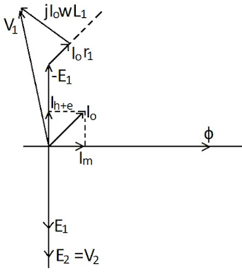 |
| Phasor diagram of real transformer operation under no-load |
Related topics>>>


Comments
Post a Comment
If you have any doubts, please let me know