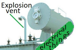
Different parts of the transformer are:-
- Transformer tank
- High voltage and low voltage bushings
- Cooling tubes / Fins / Radiator banks
- Cooling fans
- Conservator tank
- Explosion vent
- Oil drain valve
- Oil inlet / filling valve
- Temperature / Pressure gauges
- Name plate
- Control panel and tap changer
Transformer Tank
The entire core and coil assembly of oil filled transformer is enclosed by metal tank made mostly of welded mild steel sheets or sometimes aluminum. Purpose of the tank is to hold the oil and to provide a protective causing around the internal parts.
The tank is earthed so as to prevent external bodies from getting electrocuted and to prevent electromagnetic noise to escape from inside the transformer and interfere with outside equipments in the vicinity of the transformer.
Transformer tanks must be air-tightly sealed for it to isolate its content from any atmospheric contaminants.
Sufficient clearances are kept between the outer surface of outermost winding and inside walls of the tank. Clearances are also provided between the top of bottom of core and upper and lower surfaces of the tank respectively.
For, small transformers, not completely filled with oil, rectangular tanks are used, while for larger transformers, completely filled with oil, two sides of the tank are made of semicircular shape to reduce the amount of oil to be used.
 |
| Schematic diagrams of transformer tank |
Bushings
Bushings are meant to insulate the overhead lines from the earthed tank as these conductors have to pass through the top of the tank to get connected to the winding terminals inside.
Bushings are made of porcelain or china clay and can be either solid type or oil filled type or capacitive type depending on the voltage range. Size of low voltage bushings are usually smaller as compared to the high voltage bushings.
Conservator tank
This is a cylindrical tank placed just at the top or at the upper portion of the main tank and is fixed on the tank lid. Conservator is partly filled with oil and remaining space at the top being taken up by atmospheric air in free breathing transformers. A pipeline fitted at the bottom of the conservator connects it with the main tank.
Function of the conservator is to store the excess oil that is produced due to volume expansion of oil in the main tank as a result of rise in temperature. When the oil inside the main tank gets heated, it expands and the excess oil flows out to get accumulated in the conservator.
When the load on the transformer reduces, its temperature goes down, and the oil level drops due to contraction.
While the main tank is completely sealed, the conservator tank is connected to the atmosphere so that the top level of oil at the conservator is at the same pressure as atmosphere.
If no conservator is used, then expanded volume of the oil inside the sealed main tank will create abnormally high pressure the main tank walls may burst out.
 |
| Conservator tank |
Breather
Main function of the breather is to absorb moisture from the air during in-breathing process of the transformer. Breather is fitted in the pipeline that connects the air inside the conservator tank with the ambient air as shown in figure.
Inside the breather, some hygroscopic substances like silica gel and fused calcium chloride are used.
When load on the transformer reduces and its temperature goes down, contraction of oil takes place. Oil from the conservator goes into the main tank. At this time, the pressure of air above the in conservator falls below the ambient. As a result, air will be drawn into the conservator due to the partial vacuum created there. This air while entering through the breather has to pass through the hygroscopic materials placed inside the breather. The moisture present in this air is absorbed by CaCl2 or silica gel from the incoming air and thus sludge formation inside the transformer tank is prevented.
 |
| Breather |
Explosion vent
Explosion vent is provided to protect the transformer from bursting out due to excessive pressure of gas.
During any fault inside the transformer, there will be an accumulation of gas in large amount inside the transformer tank. Normally, the tank is designed to withstand a pressure of 5 psig at the bottom. So, there lies the possibility of mechanical failure if pressure exceeds a certain limit.
Explosion vent is provided with a diaphragm at its mouth. The diaphragm is made of a brittle material.
When pressure inside the transformer tank exceeds a certain limit, the diaphragm bursts and allows the accumulated gas and extra oil to escape outside.
The diaphragm is generally made of glass, and is covered by a wire net, so that no one can break it by throwing stones from outside.
The mouth of the explosion vent is bent in a downward direction, so that in case of bursting out of the diaphragm, the oil can only spread in a narrow region.
Cooling tubes / Fins / Radiator Banks
Heat generated inside the transformer due to various power losses need to be dissipated away to the atmosphere in order to prevent damage to the insulation.
Based on the coolant used, the cooling methods can be classified into:-
- Air cooling
- Oil and Air cooling
- Oil and Water cooling


Comments
Post a Comment
If you have any doubts, please let me know